TRHT

Custom EV PDU engineering

custom EV PDU · Product category / custom-engineering capability

Custom EV Power Distribution Units for Project-Specific Vehicle Platforms

TRHT works with vehicle OEM and system teams to define custom high-voltage distribution around the vehicle architecture, load map, packaging envelope, and control requirements. Final ratings, interfaces, and validation scope are confirmed from project data.

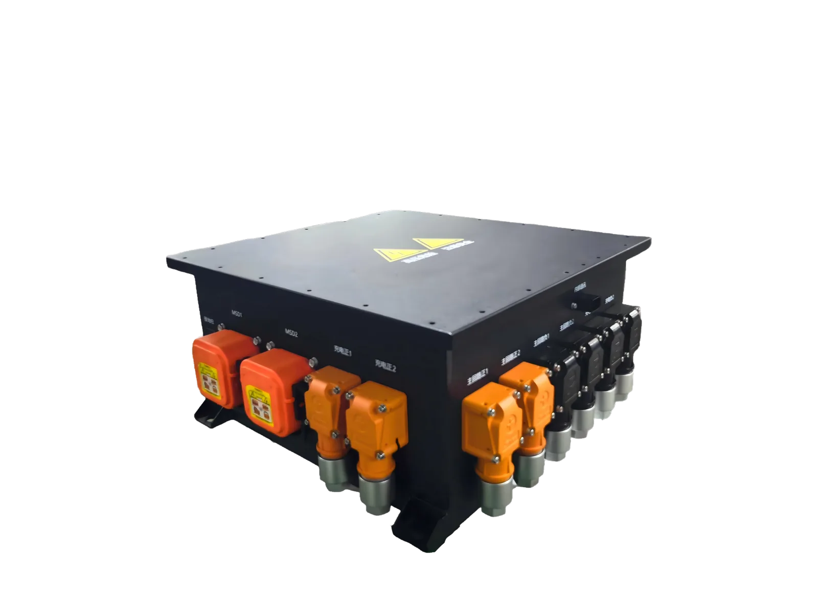
TRHT custom EV high-voltage power distribution unit

What an EV PDU does in a high-voltage vehicle system

Distribution, switching, protection, and interface roles

An EV PDU can coordinate high-voltage paths from the battery to traction, charging, conversion, thermal, and auxiliary loads. The component mix is selected around the vehicle electrical architecture.

Why architecture varies by vehicle project

Voltage window, continuous and peak duty, load branches, fault strategy, connector layout, enclosure space, cooling, and control ownership change from one platform to another.

TRHT custom EV PDU engineering scope

Contactor, pre-charge, fuse, sensing, HVIL, and communications

Project-dependent integration may include contactors, pre-charge, fuses, current or voltage sensing, HVIL, and CAN/LIN or discrete control interfaces where required.

Busbars, connectors, outputs, enclosure, and installation packaging

Busbar routing, connector selection, branch outputs, mounting, sealing targets, and service access are mapped to the vehicle envelope rather than assumed from a generic model.

Information required to evaluate a custom EV PDU

Voltage/current duty and high-voltage load list

Share the nominal and operating voltage window, continuous and peak current with duration, branch loads, protection ownership, and pre-charge requirements.

SLD, control logic, interfaces, environment, and mechanical envelope

An SLD, BMS/VCU interface expectations, CAN/LIN needs, connector preferences, cooling, environment, mounting space, and project stage help engineering define a reviewable starting point.

Development and validation planning

Requirement review through prototype planning

The normal path is requirement capture, architecture review, mechanical/electrical definition, prototype planning, and alignment on acceptance criteria.

DVP&R and EOL as project-defined deliverables

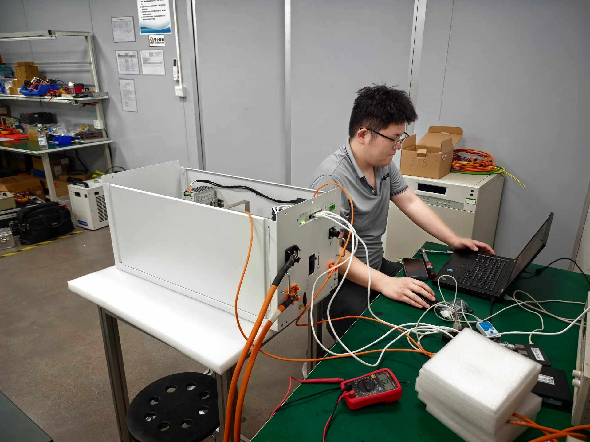
DVP&R and end-of-line checks are planned against the approved configuration. Existing testing visuals show process context, not completed validation for every product.

How to start an EV PDU RFQ

Submit the available SLD or load map, voltage and current duty, branch and protection requirements, control interfaces, packaging constraints, project stage, sample context, and target production context. Engineering can then identify the information still needed before a technical proposal.

Evidence context

Real TRHT engineering and testing context

These visuals support a conservative engineering and workmanship context. They do not identify an exact model or prove a universal rating, certification, customer case, or completed validation result.

TRHT functional testing of a high-voltage power unit

Buyer questions

Frequently asked questions

What information is required to customize an EV PDU?

Provide the voltage window, continuous and peak current, load list, SLD, protection and pre-charge requirements, control interfaces, connectors, installation envelope, environment, project stage, and quantity context.

What functions can an EV PDU integrate?

Depending on the architecture, the design may integrate contactors, pre-charge, fuses, sensing, HVIL, busbars, connectors, branch outputs, and CAN/LIN or discrete interfaces.

How is an EV PDU different from a BDU?

An EV PDU generally distributes and protects high-voltage power to vehicle loads, while a BDU/BJB is typically centered on battery isolation, main connection, pre-charge, and pack service functions. The boundary is defined by the vehicle architecture.

Can TRHT support project-specific CAN or LIN interfaces?

Communication and discrete control requirements can be reviewed as part of the project interface definition; the final mapping depends on the BMS/VCU architecture.

What determines fuse, contactor, and pre-charge selection?

The voltage window, continuous and peak duty, fault data, load capacitance, switching sequence, thermal conditions, service strategy, and applicable acceptance criteria determine the selection.

What files should be included in an EV PDU RFQ?

An SLD, load list, interface definition, preliminary mechanical envelope, control logic, environment, protection expectations, project stage, and sample or production context are useful starting inputs.
Continue your review

Related TRHT resources

Move from category understanding to architecture review, factory context, or an RFQ conversation.

WhatsAppRFQ